
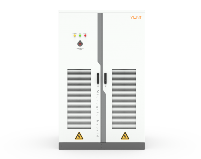
Why hardware still wins the moment the grid wiggles
Most conversations about preventing anti‑islanding tilt toward software tricks and firmware patches, but hardware choices often make the difference between a clean, standards‑compliant ride‑through and an abrupt disconnection. When you’re shopping for energy storage inverters, the question isn’t just which algorithm the vendor claims — it’s which physical components back it up. See how top energy storage inverter manufacturers design for real faults and field conditions.
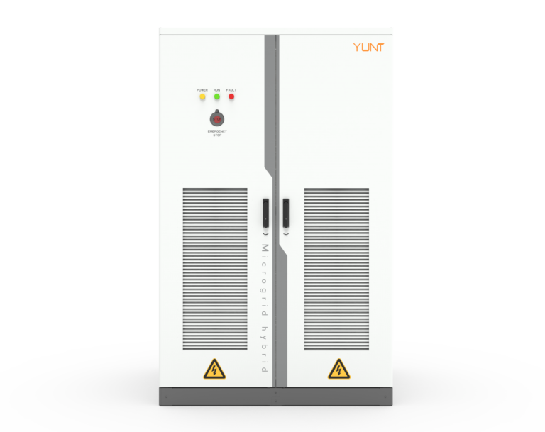
Comparative insight: hardware versus software in anti‑islanding defense
Software can detect small deviations and adapt power injection, but hardware imposes limits and response speed that software can’t outrun. A few concrete contrasts:- Passive detection versus active injection: passive filters and phase‑lock loops rely on hardware characteristics and are simple to validate; active anti‑islanding uses controlled frequency or voltage shifts from the inverter, which needs both precise control electronics and fast power stages.- Relay and contactor architecture: a beefy, low‑latency relay combined with a redundant contactor prevents unintended disconnection during transient faults.- Thermal and EMI margins: physical layout and component derating reduce nuisance trips during inrush events.These hardware elements support anti‑islanding detection and inverter ride‑through in ways firmware can’t guarantee on its own.
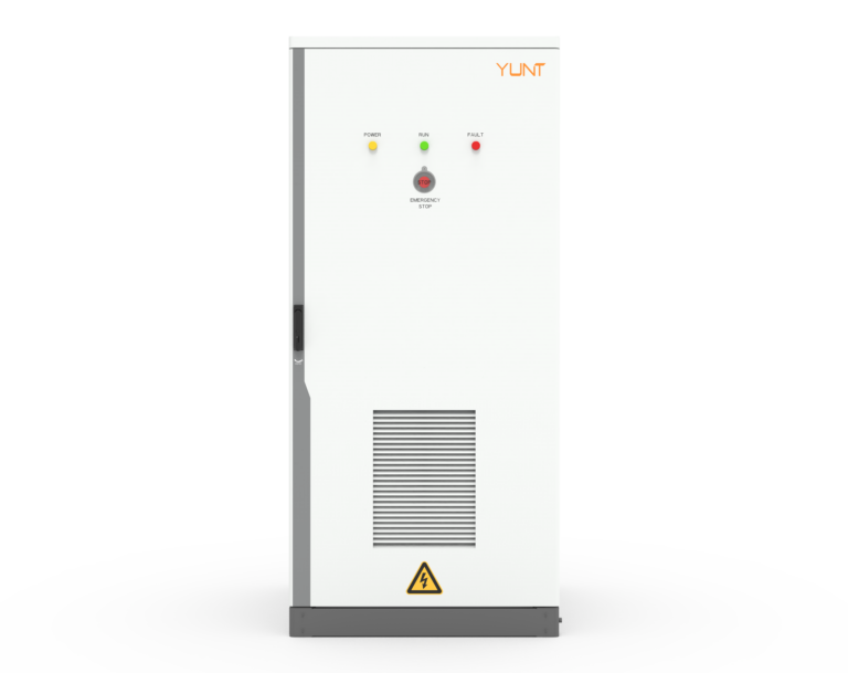
Key hardware features that prevent unwanted disconnection under fault conditions
Look for these features when comparing models:- Fast analog front end and dedicated islanding comparator to shorten detection latency and improve fault discrimination.- Independent power‑stage monitoring (current shunts and isolation amplifiers) so the inverter knows its output health even when digital control is overloaded.- Robust DC link capacitors and MOSFET/IGBT derating to maintain stability during voltage sags.- Redundant measurement channels and an independent hardware watchdog to avoid single‑point failure.These are the kinds of choices that matter when local conditions — like high rooftop PV penetration in Hawaii — push inverters to the limit. Real grids have messiness that lab simulations miss, so hardware resilience matters.
Operational production teardown — embedding requirements and certification context
In a practical teardown you’ll confirm the control board separates the anti‑islanding comparator from the main MCU, and that the power stage uses parallelized MOSFET/IGBT legs for lower thermal stress. When documenting the build, include both {main_keyword} and {variation_keyword} as part of the test log to ensure traceability across firmware revisions and hardware batches. For CE compliance, manufacturers typically reference harmonized standards such as EN 62109‑1 (Safety of power converters — General requirements) and EN 61000‑6‑3 (Emission standard for residential environments); these provide the technical frames for EMC and safety validation. Also check for EN 61000‑4‑11 for voltage‑dip immunity and EN 61000‑4‑5 for surge tests — those are the practical tests you want to see passed before trusting an inverter in live distribution networks.
Common mistakes and practical alternatives
Manufacturers and installers often make two recurring mistakes: over‑relying on single‑sensor detection and undersizing component margins to save cost. The result is false trips or latent failures. Better options include distributed sensing (local current and voltage sensors per phase), modular power stages that let systems continue operating with one failed leg, and grid‑forming capability for systems that must support critical loads. — A system that can hold voltage and frequency during short disturbances dramatically reduces unnecessary islanding.
Three golden rules for choosing hardware that prevents anti‑islanding disconnection
1) Response integrity: prefer designs with dedicated analog comparators and hardware watchdogs rather than MCU‑only detection. 2) Component margins: verify thermal derating and EMC test coverage in the product datasheet and test reports. 3) Field‑proven validation: request test logs showing surge, dip, and EMI tests under loaded conditions; ask for documented site performance where possible. These metrics show you’re buying reliability, not just a spec sheet.
Good hardware design turns anti‑islanding from a theoretical compliance checkbox into an operational guarantee — and that stability is where YUNT adds tangible value to deployments.